This article provides the recommended maintenance schedule and procedures for the NXB-CTL-212-005 Safety Controller to ensure continued SIL 3/PLe compliance and reliability.
Related Products
Tools Required
- Digital Multimeter (DMM)
- Insulated flat-head screwdriver
- Anti-static wrist strap
- Lint-free cloths
- Compressed air
Article
Overview
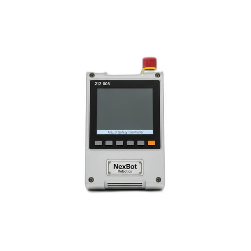
Regular maintenance of the NexBot Robotics 212-005 SIL 3 Safety Controller (SKU: NXB-CTL-212-005) is critical for maintaining the integrity of your robotic cell's safety system. This component is central to processing inputs from all safety devices and must be verified periodically to ensure it functions as designed. Adhering to this maintenance schedule helps prevent unexpected downtime and ensures the continued protection of personnel and equipment. This procedure is applicable to systems incorporating NexBot R-20, R-50, C-10, and S-5 series robots.
Maintenance Schedule
- Interval: Every 6 months or 2,000 operational hours, whichever comes first.
- Environment: For environments with high levels of dust, vibration, or temperature fluctuations, consider reducing the interval to every 3 months.
Required Tools and Parts
Tools:
- Digital Multimeter (DMM) with probes
- Insulated flat-head screwdriver (for terminal blocks)
- Anti-static wrist strap
- Lint-free cloths
- Can of compressed air (electronics-safe)
Parts:
- No routine replacement parts are required for this procedure. Inspect cabling such as the EtherCAT FSoE cable (e.g., NXB-CBL-NET533-004) for wear and replace only if damaged.
Procedure
WARNING: Ensure the robotic cell and all related machinery are powered down and locked out/tagged out (LOTO) according to your facility's safety procedures before beginning any maintenance work. The NXB-CTL-212-005 controller operates on 24VDC, but it controls high-power systems.
Step 1: Preparation and Safety
- Perform a complete LOTO procedure on the main electrical disconnect for the robot controller cabinet.
- Wait at least 5 minutes for any stored energy in capacitors to dissipate.
- Put on an anti-static wrist strap and connect it to a verified grounding point on the cabinet chassis.
Step 2: Visual and Physical Inspection
- Open the control cabinet and locate the NXB-CTL-212-005 Safety Controller.
- Visually inspect the controller's housing for any signs of physical damage, such as cracks, discoloration, or melting.
- The controller has an IP20 rating, meaning it is not protected from liquids and has limited protection from dust. Check for excessive dust or debris accumulation on the housing and ventilation slots. If present, use a can of compressed air to gently clean the exterior.
- Verify that the controller is securely mounted to its DIN rail or mounting plate. Gently attempt to move the unit; it should not be loose.
Step 3: Connection Integrity Check
- Inspect all wired connections to the controller's terminal blocks. Ensure each wire is fully seated and there are no stray strands.
- Using an insulated screwdriver, gently check the tightness of each terminal screw. Do not overtighten; they should be snug.
- Inspect the EtherCAT FSoE cable connections. Ensure the connectors are fully seated and the locking tabs are engaged. Check the cable for any signs of kinking, abrasion, or damage.
Step 4: Power Supply Verification
- Temporarily and safely remove the LOTO to re-apply power to the control cabinet only. Do not enable robot motion.
- Set your digital multimeter to measure DC voltage.
- Carefully probe the 24VDC power input terminals on the NXB-CTL-212-005 controller.
- The voltage reading should be within ±5% of 24VDC (typically 22.8VDC to 25.2VDC). A reading outside this range may indicate a failing power supply unit, which should be investigated separately.
- Once the voltage check is complete, re-apply the LOTO procedure to the cabinet.
Verification
Step 1: Power-On Status Check
- Remove all tools from the cabinet and ensure the door is securely closed.
- Remove the LOTO and restore power to the robotic cell.
- Observe the status LEDs on the front of the NXB-CTL-212-005 controller. Refer to the product's technical manual for a detailed LED status guide. A solid green 'POWER' and 'RUN' LED typically indicates normal operation with no faults present.
Step 2: Functional Safety Test
- With the system powered on but stationary, systematically test each safety input connected to the controller.
- Emergency Stop: Press an E-stop button within the cell. Verify that the controller registers the input, robot drives lose power, and the appropriate fault is displayed on the HMI.
- Light Curtain: Interrupt the beam of a light curtain. Verify the system enters a safe state immediately.
- Safety Gate: Open a safety gate. Verify that all hazardous motion is stopped and cannot be restarted until the gate is closed and the system is reset.
- After each test, reset the safety circuit and confirm that the controller returns to a normal operational state.
Step 3: Documentation
- Record the date of the maintenance, the name of the technician performing the work, and the results of the inspection and functional tests in your maintenance log.
- Note any anomalies, even if they did not result in a failure, for future reference.
If the NXB-CTL-212-005 controller fails any of these verification steps, remove it from service immediately and consult the troubleshooting guide or contact technical support.