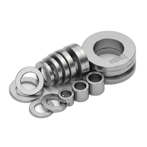
This article provides the procedure for inspecting and replacing washers and spacers in NexBot robot joints (J2, J3, J6) using the NXB-GEN-833-013 set to maintain alignment and reduce backlash.
Related Products
Tools Required
- Calibrated torque wrench
- Metric hex key set
- Digital calipers or micrometer
- Feeler gauges
- Lint-free cloths
- Appropriate PPE (Safety glasses, gloves)
- Lockout/Tagout (LOTO) kit
Article
This document outlines the standard maintenance procedure for inspecting and replacing shims, washers, and spacers in critical NexBot robotic arm joints using the NexBot Robotics 833-013 Washer And Spacer Set (Stainless Steel). Proper joint spacing is essential for positional accuracy, repeatability, and the long-term mechanical health of the robot. This procedure should be performed by qualified technicians when addressing issues of joint backlash, positioning errors, or as part of a major service interval.
Maintenance Schedule
This maintenance is not typically part of a routine daily or weekly check. It should be performed under the following conditions:
- During scheduled major service intervals (e.g., annual or multi-thousand-hour service), as specified in the robot's primary service manual.
- When troubleshooting and diagnosing excessive mechanical backlash or 'slop' in the J2, J3, or J6 axes.
- After a joint motor or gearbox replacement where component stack-up may have been affected.
- If positioning repeatability tests show a degradation in performance isolated to a specific joint.
Parts Needed
- NXB-GEN-833-013: NexBot Robotics 833-013 Washer And Spacer Set (Stainless Steel). This set contains a calibrated assortment of high-precision washers and spacers required for the procedure.
- Appropriate thread-locking compound (refer to robot service manual for specification).
- Approved cleaning solvent (e.g., Isopropyl Alcohol).
Safety Precautions
WARNING: Failure to de-energize the robot can result in serious injury or death. Always follow established safety protocols for your facility.
- Power Down: Completely power down the robot and its controller.
- Lockout/Tagout (LOTO): Apply LOTO devices to the main electrical disconnect for the robot cell in accordance with safety regulations.
- De-energize: Verify that all electrical, pneumatic, and hydraulic energy sources are at a zero-energy state.
- Secure Manipulator: If necessary, use certified overhead lifting equipment or mechanical braces to support the robot arm to prevent unexpected movement or collapse when joint components are removed.
- Personal Protective Equipment (PPE): Wear appropriate PPE, including safety glasses and protective gloves.
Procedure
This procedure provides a general workflow applicable to compatible joints (J2, J3, J6) across various NexBot series like the R-20, R-50, C-10, and S-5. Always consult the specific service manual for your robot model for detailed diagrams and torque specifications.
Step 1: Access the Joint
- Move the robot to a designated maintenance position that provides safe and clear access to the target joint.
- Carefully remove any plastic covers, cable management brackets, or external components obstructing access to the joint's mechanical housing and fasteners.
Step 2: Initial Inspection
- With the joint covers removed, visually inspect the area for signs of excessive wear, metal shavings, or lubricant leakage, which may indicate a more severe issue.
- Manually attempt to move the robot link connected to the joint. Note any perceptible 'clunk' or backlash. This will serve as a baseline for post-service verification.
Step 3: Component Disassembly
- Identify the primary fasteners for the component that requires shimming (e.g., the gearbox output flange or bearing housing).
- Carefully loosen and remove the fasteners in a star or crisscross pattern to ensure even pressure release.
- Gently separate the components. Be prepared for existing shims or washers to be present. It is critical to collect and measure these original parts.
- Note the exact order and orientation of all removed components, including the original spacers.
Step 4: Cleaning and Measurement
- Thoroughly clean the mating surfaces of the disassembled components, as well as the original washers, using a lint-free cloth and an approved solvent.
- Using a calibrated digital caliper or micrometer, measure the thickness of the original washer/spacer stack.
- Refer to the robot's service manual for the required clearance or preload specification for that specific joint. This value is critical.
- Compare the required specification with your measurements to determine how much shim thickness needs to be added or removed.
Step 5: Select and Install New Hardware
- From the NXB-GEN-833-013 set, select the combination of washers and spacers that achieves the precise thickness required to meet the specification. The high-grade 304 Stainless Steel construction ensures dimensional stability and corrosion resistance.
- Place the new washer/spacer stack onto the designated surface, ensuring they are flat and correctly seated.
Step 6: Reassembly and Torquing
- Carefully reassemble the joint components, ensuring proper alignment.
- Apply the specified thread-locking compound to the fastener threads if required by the service manual.
- Install the fasteners finger-tight, then use a calibrated torque wrench to tighten them to the manufacturer's specified torque value in the recommended sequence (typically a star pattern).
Verification
- Mechanical Check: Manually articulate the joint to ensure it moves smoothly without binding or excessive resistance.
- Power Up: Remove LOTO devices and power the robot system back on, following standard startup procedures.
- Jogging: In a slow manual mode (T1), jog the affected joint through its full range of motion. Listen for any abnormal noises and watch for any motor strain or controller errors.
- Repeatability Test: If available, run the robot's position repeatability or calibration routine to confirm that the joint's accuracy is now within acceptable limits.
- Final Inspection: Reinstall all covers and components removed during the procedure. Run a test program to validate the repair under normal operating conditions.