Step-by-step procedure for performing a major joint overhaul on NexBot R-20 and R-50 series robots using the NXB-KIT-762-003 hardware kit to restore positioning accuracy and eliminate backlash.
Related Products
Tools Required
- Torque wrench (10-50 Nm)
- Metric hex bit socket set
- Feeler gauge set
- Dial indicator with magnetic base
- Soft-faced mallet
- Dowel pin puller
- Lint-free cloths
- Industrial degreasing solvent
Article
This article provides a detailed procedure for the scheduled maintenance overhaul of major articulated joints on NexBot R-20 and R-50 series robots. The process utilizes the NexBot Vision 762-003 Joint Overhaul Hardware Kit (NXB-KIT-762-003) to replace high-stress fasteners and precision alignment components. Performing this maintenance is critical for addressing excessive joint backlash, restoring mechanical rigidity, and ensuring the robot maintains its specified positioning accuracy over its operational lifespan.
Schedule
This procedure should be performed as part of a major service interval, typically recommended every 8,000 operational hours or 24 months, whichever comes first. It should also be performed immediately if joint backlash is measured to be outside of the tolerances specified in the robot's service manual.
Parts and Tools Needed
Parts Required
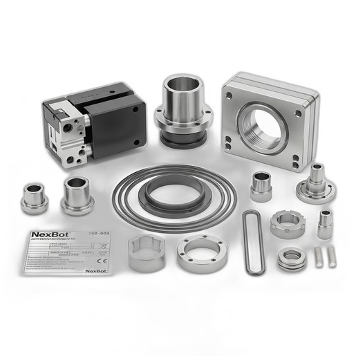
- One (1) NXB-KIT-762-003 NexBot Vision 762-003 Joint Overhaul Hardware Kit, which includes:
- High-Tensile Socket Head Cap Screws (Grade 12.9, M8 x 40mm)
- High-Tensile Socket Head Cap Screws (Grade 12.9, M6 x 25mm)
- Hardened Steel Precision Alignment Dowels (6mm Dia.)
- Stainless Steel Shim Set (0.05mm, 0.10mm, 0.25mm thicknesses)
- Joint Access Cover Plates (Set of 2)
- Vibration-Resistant Lock Washers
Tools Required
- Calibrated Torque Wrench (range covering 10-50 Nm)
- Metric Hex Bit Socket Set (including 5mm and 6mm sizes)
- Feeler Gauge Set
- Dial Indicator with Magnetic Base
- Soft-faced Mallet
- Dowel Pin Puller (optional, but recommended)
- Industrial Degreasing Solvent
- Lint-free Cloths
- Appropriate Personal Protective Equipment (PPE): Safety glasses, gloves
Safety Precautions
WARNING: Failure to follow safety procedures can result in serious injury or death, and damage to the equipment.
- Lockout/Tagout (LOTO): Disconnect and lock out all power sources (electrical, pneumatic, hydraulic) to the robot controller and manipulator before beginning any work.
- Support the Manipulator: Before loosening any joint fasteners, the robot arm must be mechanically supported using an overhead crane or appropriately rated blocking to prevent uncontrolled movement or collapse.
- Residual Energy: Be aware of stored energy in brakes or pneumatic systems. Follow the robot-specific procedure for releasing stored energy safely.
Procedure
This is a general procedure. Always consult the specific service manual for your robot model for detailed diagrams and specifications.
Step 1: Preparation and Disassembly
- Move the robot to a designated maintenance position that provides safe and clear access to the target joint.
- Execute the full LOTO procedure.
- Securely support the arm sections on either side of the joint being serviced.
- Remove the old Joint Access Cover Plates to expose the joint fasteners.
- Using a star or crisscross pattern, progressively loosen and remove all M8 and M6 socket head cap screws securing the joint. Discard the old screws and lock washers.
- Carefully separate the joint housing. This may require removing an actuator or motor assembly first. Refer to the service manual.
- Extract the old alignment dowels. If they are tight, use a dowel pin puller. Avoid using pliers, which can damage the housing surfaces.
Step 2: Cleaning and Inspection
- Thoroughly clean all mating surfaces of the joint housing with an approved degreasing solvent and lint-free cloths. Ensure all old sealant, grease, and debris are removed.
- Inspect the cleaned surfaces for any signs of damage, fretting corrosion, or cracks. If significant wear is found, contact NexBot Robotics technical support.
Step 3: Reassembly and Shimming
- Gently tap the new Hardened Steel Precision Alignment Dowels from the kit into place using a soft-faced mallet. Ensure they are fully seated.
- Temporarily re-seat the joint housing without fasteners. Use a feeler gauge to measure the gap between the mating surfaces at several points around the joint.
- Select the appropriate combination of shims from the Stainless Steel Shim Set to achieve the precise clearance or preload specified in the robot's service manual. The goal is to eliminate play without binding the joint.
- Place the selected shims and re-assemble the joint. Install the new High-Tensile Socket Head Cap Screws and Vibration-Resistant Lock Washers from the kit. Thread them in by hand until they are finger-tight.
Step 4: Torquing Sequence
- Following a star or crisscross pattern, tighten the screws in stages to ensure even clamping pressure.
- Stage 1: Torque all screws to 50% of their final value.
- M6 Screws: Target ~7.5 Nm
- M8 Screws: Target ~17.5 Nm
- Stage 2: Torque all screws to 100% of their final value.
- M6 Screws (Grade 12.9): 15 Nm
- M8 Screws (Grade 12.9): 35 Nm
Note: These are typical values. Always confirm the exact torque specification in your robot's service manual.
- Reinstall any actuator/motor assemblies that were removed, following their specific torque procedures.
- Install the new Joint Access Cover Plates from the kit.
Verification
- Remove all mechanical supports and tooling from the robot's work envelope.
- Reverse the LOTO procedure and restore power to the robot.
- Backlash Check: Mount a dial indicator on a static part of the robot (e.g., the link before the serviced joint) with the probe tip touching the link after the serviced joint. In manual mode, command small, slow, back-and-forth movements of only the serviced joint. The measured backlash on the dial indicator should be within the specification (typically < 0.1 mm).
- Robot Mastering: Perform a full robot mastering or calibration procedure as outlined in the programming manual. This is mandatory after mechanical service to ensure TCP accuracy.
- Run the robot through a test program at low speed, listening for any unusual noises and observing for smooth motion before returning it to production service.