This article provides step-by-step instructions for the safe and correct installation of the NexBot Robotics DC112-007 DC Servo Motor on compatible industrial robot arms.
Related Products
Tools Required
- Lockout/Tagout (LOTO) kit
- Safety glasses
- ESD-safe gloves
- Metric hex key set
- Torque wrench with appropriate sockets
- Small flathead screwdriver
Article
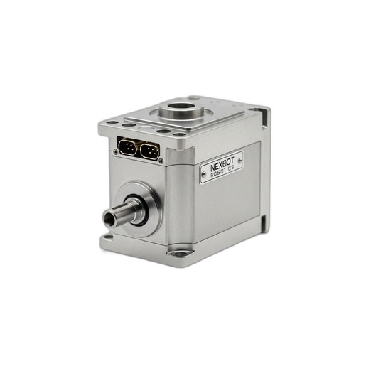
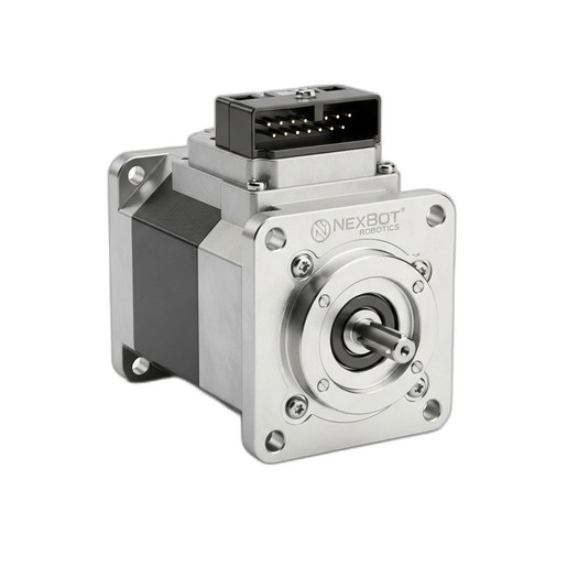
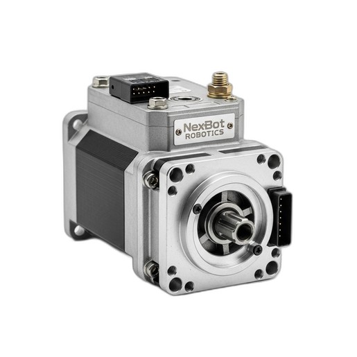
This document outlines the standard procedure for installing the NexBot Robotics DC112-007 DC Servo Motor (SKU: NXB-SRV-DC112-007). This high-precision, IP67-rated motor is designed for demanding applications, commonly found in the J6 (wrist) joint of NexBot R-20 series articulated robots. Following these instructions ensures the component is installed safely and functions according to its specified performance of 7 Nm torque and IO-Link communication.
Prerequisites
Before beginning the installation, ensure all prerequisite conditions are met to guarantee safety and prevent equipment damage.
Safety Precautions
- Lockout/Tagout (LOTO): The robot and its controller must be fully de-energized and locked out according to your facility's established LOTO procedures. All sources of electrical, pneumatic, and hydraulic power must be isolated and verified at a zero-energy state.
- Personal Protective Equipment (PPE): Wear appropriate PPE, including safety glasses and ESD-safe gloves, throughout the entire procedure.
- Robot State: The robot arm should be moved to a safe, stable position, preferably its home or a designated maintenance position, before powering down.
Parts and Tools Verification
- Component Check: Verify that the new motor is the correct part: NXB-SRV-DC112-007. Inspect the new motor for any signs of shipping damage to the housing, shaft, or connectors.
- Tools: Gather all required tools listed in the 'Tools Required' section of this document.
Step-by-Step Installation Instructions
Follow these steps carefully. Refer to the specific service manual for your robot model (e.g., NexBot R-20 series) for detailed diagrams and fastener torque specifications.
Step 1: Power Down and Isolate the Robot
- Ensure all running programs are stopped.
- Power down the robot controller using the standard shutdown procedure.
- Isolate the main electrical supply to the controller cabinet and apply your LOTO device and tag.
- Verify that all system power is off.
Step 2: Access the J6 Joint Assembly
- Carefully remove the protective covers from the robot's J6 joint assembly. This may require a hex key or screwdriver.
- Set the covers and fasteners aside in a clean, organized manner.
Step 3: Disconnect the Old Motor
- Locate the electrical and communication connectors on the existing servo motor.
- Carefully disconnect the 24VDC power cable and the IO-Link communication cable. Most connectors have a locking tab or ring that must be released before pulling.
- Gently move the cables out of the way to provide clear access to the motor's mounting bolts.
Step 4: Remove the Old Motor
- Identify the mounting bolts securing the motor to the joint flange. There are typically three or four bolts.
- Using the correct size hex key, loosen the bolts in a star pattern to release pressure evenly.
- Once all bolts are removed, carefully slide the motor out of its mounting position. Be aware that the motor shaft is coupled to the joint's gearbox; a slight rocking motion may be needed to disengage it.
Step 5: Prepare and Mount the New Motor
- Unbox the new NXB-SRV-DC-112-007 motor. Verify the motor shaft is clean and free of debris.
- Align the motor shaft key with the keyway on the gearbox input shaft.
- Carefully slide the new motor into position, ensuring it sits flush against the mounting flange without being forced.
- Insert the mounting bolts by hand to ensure they are not cross-threaded.
- Tighten the bolts in a star pattern to the torque value specified in the robot's primary service manual. Do not overtighten.
Step 6: Connect Electrical and Communication Cables
- Reconnect the 24VDC power cable to the corresponding connector on the new motor. Ensure it is fully seated and the locking mechanism engages.
- Reconnect the IO-Link communication cable. The connector is keyed to prevent incorrect insertion.
- Secure the cables to any existing cable management clips to prevent snagging during robot operation.
Step 7: Reassemble Joint Covers
- Reinstall the J6 joint covers that were removed in Step 2.
- Ensure all fasteners are secured properly.
Verification
After installation, perform the following steps to verify proper functionality.
Step 1: Power On the System
- Ensure all personnel are clear of the robot's work envelope.
- Remove your LOTO device and tag from the main power disconnect.
- Power on the robot controller.
Step 2: Check for Faults
- Observe the teach pendant or control interface for any new alarms or faults. Specifically, check for any errors related to the J6 axis drive system.
- If the IO-Link communication is established correctly, the controller should recognize the new NXB-SRV-DC-112-007 motor.
Step 3: Test Joint Functionality
- Set the robot to a low manual speed (e.g., 10% or less).
- Using the teach pendant, carefully jog the J6 axis in both positive and negative directions.
- Listen for any unusual noises and watch for smooth, controlled motion. Confirm the axis moves as commanded.
Step 4: Perform Homing and Calibration
- Replacing a servo motor often requires the robot's mastering or calibration data to be updated for that axis.
- Perform the robot's standard homing procedure.
- Consult your robot's programming manual for the specific axis calibration or mastering procedure and execute it if required for positional accuracy.